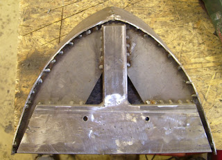
Application of raised chrome parts and hex-nuts to the pilot
The hex-nut row at the bottom of the pilot will not be applied - it interferes with the welded frame inside as well as it would weaken the pilot bottom.
3/30/2013
3/24/2013
New pictures of assembled M-10005 A-unit
Finally a sunny day made it possible to assemble the A-unit outside and make a photo-session as well as some measurements with the unit on rails (the critical dimension is the distance of the pilot to the top of the rails).
And a detailed view of the compressed air cooler on the top of the unit
The future engineer also took the opportunity to pose with his workhorse (some older guys might recognize the old 'Big Jim'-action figure).
And a detailed view of the compressed air cooler on the top of the unit
The future engineer also took the opportunity to pose with his workhorse (some older guys might recognize the old 'Big Jim'-action figure).
3/23/2013
M-10005: pilot's construction
Another 'critical' & distinctive part has been basically finished - the pilot.
While the circumference shape changes from almost tangent (at the unit's side) with a decreasing radius into the tip of the item the vertical orientation is twisted from almost vertical (once again at the side) into a significant angle at the tip.
From a test-sample from wood and cardboard the basic shapes of ribs/frames at the upper and lower position were evaluated.
First a basic main frame from square tubes was constructed and test-fitted onto the unit's chassis.
Flat bar irons (thickness app. 1/10 of an inch) were welded and ground into the determined shape of the ribs. These were welded onto the basic main.
The pilot's panels were cut from a iron stove-pipe (8" diameter) and bent into the shape given by the ribs (with deliberate use of a hammer). The panels were welded to the ribs finally while fixed by heavy clamps.
Finally the pilot was cut & ground into the prototypical shape.
Some sanding was necessary to adapt the overlap of the shell to the new pilot - some re-laminating of the overlapping area will be necessary. But basically the pilot now fits the shell.
Subscribe to:
Comments (Atom)


