8/28/2012

M-10005: front grill

During the very tedious work on paint touch-ups on the KM caused by a 'catastrophe' during the attempt of using liquid tape as simulation of the rubber-gasket on the shell , I got some solace by working on the M-10005's front grills...it seems that they are close to the prototype and even (almost) symmetrically on left and right. Since the front end of the nose consists of compound curves in every direction, shaping the frame and the horizontal ribs was a trial-and error process.


Additionally the door frames and further grills on the side were attached.

8/13/2012

Update on KM's paint-job

Almost finished (some faults caused by over-spray have to be corrected).


Next step will be the rubber-decoupling around the cab - I intend to use liquid electrical tape for this

8/07/2012

M-10005's shell - update

The housing for the headlight (copper tube) was fitted into the nose as well as the housing for the vertical warning light on the cab.


Cut-outs for the exhaust-system were made in the roof; for the photo, the roughly shaped insert part (which will carry the exhaust-muffler like a tray) was placed provisionally.

7/16/2012

Current status of the paint job on the KM

The black stripe between Aspen gold and the lower silver area is still missing.

M-10005 - shell

 Cut-out for windows and grill are roughly made....

And with the cut-out's for the front-grills...

And a look into the interior of the shell - the foam-'plug' was rather easy to remove with hot-cutter, chisel etc.


7/09/2012

EMC M-10005 - progress on shell (A-unit)

nose and cab area

side-view of nose

side-view total

6/02/2012

Painting BLW's 'Blue Goose'


Paint job isn't finished - the separation between gray and blue in the cab's door area has to be shifted a bit downwards to become straight. However, the slightly downwards orientation below the side windows is prototypically - as the slightly inclined upper separation over the side grills.
And yes, the chrome trim is missing on the nose.

5/03/2012

M-10005's shell started


Plane sides are fibre-board; nose-core is shaped from foam.
the roof will get a basic shape by extruded metal grid.
All areas will be covered with several layers of glass-fibre-material with resin..

4/15/2012

UP's M-10005 in 1/7.3 - first pictures of the chassis & trucks

I started with the trucks for the A&B unit last year, fabricated another pair of trucks for the aux power-baggage and welded the basic frames for models in winter. I already have made the two trays carrying the car-batteries (six in total, wired in series & parallel for 36V).


Each axle is powered by two 750W motors (36V) connected by chain (including an idler of app. 4:1-ration for speed-reduction/torque-increasing). However, the 750W power-designation of each motor is more or less a theoretical value, because I (hopefully) will never use or need the specified torque of this operating point.
Similar to my construction of the LWT12 the batteries are stored in lowered trays which will lead to a rather low center of gravity.

4/13/2012

Aerotrain's LWT12 - finally some kind of sound

Suffering diffculties with the public getting of the tracks I have mounted signal horns. Not the usual small electric horns of a car, but compressor-driven horns of a truck (ok, only a two-chime horn - should be a three-chime, I know). The horns are 15" and 12" long, with an almost prototypical low frequency sound (in comparison to the usual small car-horns).
The horns and the compressor are mounted in the rear of the shell's frame where the prototype's radiator would be.


View from downside of the shell with the compressor next to the horns - the system will act either as a melodical horn or produce two tones simultaneously (the option which I have chosen/wired).

2/12/2012

KM ML4000 CC - details on shell & electrical wire-harness

 The wire-harness for two power circuits (36V for motors, 12V for accessories) has been applied.
The motors are regulated by a 4QD-controller. The accessories (fans, lights, horns) are relay-controlled and switched from a hand-held box which contains the pot and switches for the motors, too.
The two horns are placed next to the cab. Behind the battery-tray a bank with relays and fuses is placed (40A main fuse for drive-line, each motor additionally fused with 20A).


On the rear there is a connector that will supply power to the shell (fans & lights).

The shell now has been fitted with hand-rails; the accompanying ladders have been attached to the frame

On the cab DRGW's distinctive rear-mirrors were attached - in contrast to the prototype the model has collapsible mirrors to avoid conflicts during transport.


12/25/2011

Update on Krauss-Maffei's ML 4000CC

I've worked on the 'power supply' and the trucks mechanisms. As mentioned before I switched to 36V-voltage provided by 3 automotive batteries wired in series (each has 55Ah).
Here's the additional sub-frame for holding the batteries - on top of the unit's main frame:

And now loaded....

Since there is need for 12V (lights, horns etc.), too, I've used the space of the 'tank' below the frame to place a small 12V battery:

Each truck is powered by a 36V, 350W-PM-motor - connected via chains and gear reduction to the outer axle.
The three axles of each truck are connected by chains:

11/30/2011

UP's EMD M-10005 'City of Denver' in 1/7.3 scale

Well, in order to have a motive-power-project in each of my preferred three gauges I'm interested in there had to be a new project on 7 1/4"-rails.
After long consideration UP's M-10005 'City of Denver' made it....
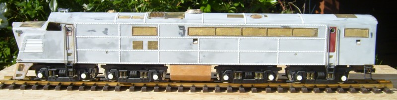
I'll follow the original version with the vertical warning light and yellow and brown painting scheme.
The scale is a bit 'stretched' to 1/7.3 which will allow me to use 5" wheels as prototype's 36 inch wheels (additionally, my old 'Big Jim' action figures can act as engineer & fireman without being too tall).
The A-unit will be powered by 4 motors, one per axle - running on 36V. I'm not sure how many batteries the unit will carry. The B-unit will be prepared for motorization, however, I'll decide this matter until first running tests of the units.
The batteries will be carried between the trucks in a lowered 'tray' so a low center of gravity will result - I hope to get similar good tracking qualities as shown by the Aerotrain.
A 5 3/4"  figure poses next to the post-war version of M-10005 (H0-scale) which is close the relation of my future model next to a 'real' 6' guy.


Currently the trucks are under construction - they will be fixed in sub-frames, which will be connected to the main frame.
The (first) riding car will be the auxiliary power-baggage car (with no power unit) - however, this is quite far away in the future.....
Photos of the frame's construction will follow, soon.

10/02/2011

Just out of the paint-shop: The 'Aerotrain'

After mounting about 17000 small nails as 'rivets' the Aerotrain was finally sent to the paint-shop.Not completely finished by now but well enough for 'posing' during today's visit of a live-steam club.


 Next step will be manufacturing of the side-frames for the wheels.

8/10/2011

some news regarding BLW's 'blue goose'

Some progress (horns, ladders, rear coupler and front trim)