
1/06/2014
M-10005 - Air-brake cylinders on trucks
The four (non-functional) air-brake cylinders per truck as well as the accompanying two pistons per cylinder (one on each side) were attached to the trucks.
1/04/2014
A-unit's front window modification
Comparison of the original shape (upper outside edge)

with the shape of the model


with the shape of the model

reveals that the radius has been too small (ok, the upper part of the frame should incorporate a slight bow, which had been on the loose frame itself but mystically vanished when it was fitted into the shell - now it's too late to correct)
The difference in the edge's radius was corrected - looks more prototypically now

Additionally brass L-sections were applied to shells' ends of the units' shells in order to get sharp, impact-resistant edges.
1/01/2014
Progress on aux.power-baggage
The details on the front-part of the car's roof (intakes, exhausts, radiators etc.) were applied:

Unfortunately the roughly finished lower skirting interferes with the shell, so the two shells as well as the parts of the roof do not line up very well (there a 'step' from the front to the middle part of the roof).
The skirting currently consists of a rounded 1/10" steel plate (a refurbished oven's tube):

So that's the current look from the side:

12/01/2013
M-10005: Further progress on engineer's car
Current status of shell & roof:

 As mentioned before, the roof is divided into three parts - the front part will be furnished with the intakes, exhausts and radiators of the two aux-diesels.
And for comparison (adjustment of the shell's height) with the B-unit


And for comparison (adjustment of the shell's height) with the B-unit

9/30/2013
M-10005: engineer's car
Of course the train has to receive a car for the engineer - according to prototype's composition this will be the auxiliary-power/baggage car #11700 that ran on the third position of the '36's prototype. It's app. 75' 10" body will turn into a model of 10'4" length. For ease of handling during transport I decided a) to separate the 'body' from the car's frame, dividing it into two parts of 5'2" length and b) to separate the roof from the body's side dividing it into three parts (avoiding a common 'break' of roof and body at the same position).
At the roof's front (app. first 2ft) the vents & exhaust of the two aux. diesels are located (of course only as simulated details). The rest of the roof should be able to carry up to three adults (engineer+two passengers) - this will give some serious design challenges on the trucks' suspension system.
First pictures...


9/01/2013
M-10005: Assembling A- & B-unit
Eventually I assembled the complete locomotive - of course there were some problems with the powered truck which still interferes with the A-unit's coupler-pocket...more cutting & grinding necessary....
Total length is app. 18.5ft


Total length is app. 18.5ft


8/30/2013
M-10005: remodeled grill, update on trucks etc.
Some new pictures of the complete model with the reworked grill (aspect ration close(r) to prototype) and the trucks fitted with coil & leaf springs; the shell been covered with gel-coat for smoothing & UV-protection of the glass-fiber surface):


8/22/2013
Rebuilding the front grill...
After checking the aspect-ration of several prototype-photos against my model it became clear that the model's front-grill is no wide enough. After a month of consideration I finally made up my mind and have started to modify he grill.
I cut through the grill vertically, removed the outer half & enlarged the opening in order to shift the outer half of the grill app. 1 1/4" apart. Finally brass stripes of appropriate shape & length has to be fit to close the missing grill work.
upper picture shows current design, lower picture is a digital mock-up of new design

6/08/2013
M-10005: B-unit & trucks' sideframes
Here are new pictures of the B-unit. At the B-end the outlets of the two steam-generators are applied - the vanes & openings directed straight to the rear end.
The side-frames of the trucks are basically assembled - the (simulated) leaf- and coil-springs and the brake cylinders are still missing.


The side-frames of the trucks are basically assembled - the (simulated) leaf- and coil-springs and the brake cylinders are still missing.


4/09/2013
M-10005: anti-climber & buffer
The anti-climber has been detailed and the buffer (made from a massive rubber block) was adapted to it's receptacle for a test. The profile of the tip of the nose was slightly revised (straightened) on the lower half.


3/30/2013
M-10005: pilot's details
Application of raised chrome parts and hex-nuts to the pilot


The hex-nut row at the bottom of the pilot will not be applied - it interferes with the welded frame inside as well as it would weaken the pilot bottom.


The hex-nut row at the bottom of the pilot will not be applied - it interferes with the welded frame inside as well as it would weaken the pilot bottom.
3/24/2013
New pictures of assembled M-10005 A-unit
Finally a sunny day made it possible to assemble the A-unit outside and make a photo-session as well as some measurements with the unit on rails (the critical dimension is the distance of the pilot to the top of the rails).


And a detailed view of the compressed air cooler on the top of the unit

The future engineer also took the opportunity to pose with his workhorse (some older guys might recognize the old 'Big Jim'-action figure).


And a detailed view of the compressed air cooler on the top of the unit

The future engineer also took the opportunity to pose with his workhorse (some older guys might recognize the old 'Big Jim'-action figure).

3/23/2013
M-10005: pilot's construction
Another 'critical' & distinctive part has been basically finished - the pilot.
While the circumference shape changes from almost tangent (at the unit's side) with a decreasing radius into the tip of the item the vertical orientation is twisted from almost vertical (once again at the side) into a significant angle at the tip.
From a test-sample from wood and cardboard the basic shapes of ribs/frames at the upper and lower position were evaluated.
First a basic main frame from square tubes was constructed and test-fitted onto the unit's chassis.
Flat bar irons (thickness app. 1/10 of an inch) were welded and ground into the determined shape of the ribs. These were welded onto the basic main.
The pilot's panels were cut from a iron stove-pipe (8" diameter) and bent into the shape given by the ribs (with deliberate use of a hammer). The panels were welded to the ribs finally while fixed by heavy clamps.
Finally the pilot was cut & ground into the prototypical shape.


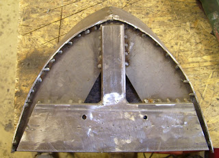
Some sanding was necessary to adapt the overlap of the shell to the new pilot - some re-laminating of the overlapping area will be necessary. But basically the pilot now fits the shell.


While the circumference shape changes from almost tangent (at the unit's side) with a decreasing radius into the tip of the item the vertical orientation is twisted from almost vertical (once again at the side) into a significant angle at the tip.
From a test-sample from wood and cardboard the basic shapes of ribs/frames at the upper and lower position were evaluated.
First a basic main frame from square tubes was constructed and test-fitted onto the unit's chassis.
Flat bar irons (thickness app. 1/10 of an inch) were welded and ground into the determined shape of the ribs. These were welded onto the basic main.
The pilot's panels were cut from a iron stove-pipe (8" diameter) and bent into the shape given by the ribs (with deliberate use of a hammer). The panels were welded to the ribs finally while fixed by heavy clamps.
Finally the pilot was cut & ground into the prototypical shape.


Some sanding was necessary to adapt the overlap of the shell to the new pilot - some re-laminating of the overlapping area will be necessary. But basically the pilot now fits the shell.


12/28/2012
M-10005: test-assembly
Some pictures of the a preliminary assembly of trucks, frame & shell (due to space restrictions this is much easier to be done outside):
side views


side views


and a better view of the exhaust manifold

12/17/2012
M-10005: updated front
Some pix of the current status of the nose-area:
A smaller headlight-tube was mounted - it starts with a circular cross-section and changes smoothly into an almost square cross-section close to the windows.
Additionally the raised section alongside the headlight 'tube' and between the grills was fabricated.


The window-frames as well as the door-frames were set into the shell - now the several portholes' frames are under construction

10/27/2012
More photos from Adliswil
The collection of 1/29-projects:

Aerotrain's LWT12:

And it's observation car:


Aerotrain's LWT12:

And it's observation car:

10/15/2012
KM ML 4000CC - update
Photos taken during the US-convention in Adliswil/Switzerland last weekend

 The trucks' side frames are still under construction - however, the main components of suspension & axle bearings are attached.


Subscribe to:
Posts (Atom)